
The marine sextant is one of those instruments that stood the test of time. It is a very reliable tool for seafarers and navigators crossing the seven oceans even before the introduction of electronic navigation.
Even with today’s global positioning system or GPS, many navigators still practice using the marine sextant as a means of position fixing. This is because, at any moment, these electronic systems can fail or produce errors.
Sextant, on the other hand, does not rely on electronic signals. This means that it is not susceptible to interference or failure, making it a reliable backup system in case of GPS malfunction.
What is a Marine Sextant?
A marine sextant is a navigational instrument used to measure the angle between two objects, typically celestial bodies such as the sun, moon, or stars, and the horizon. It consists of a metal frame with a graduated arc, a small telescope or sighting mechanism, and a movable arm or index mirror.
The primary purpose of a sextant is to determine the altitude or elevation of celestial bodies above the horizon. It is one of the tools used in marine navigation, specifically celestial navigation.
The first time I heard the word sextant, I thought it got something to do with sex. Because you know, during a long sea voyage, sailors fantasize about sex while looking at the sky. I think I almost got it right.
Turns out, the word “sextant” comes from the base Latin word “sextus“, which means sixth. Then it evolved into “sextans or sextant” meaning “one-sixth or sixth part”. This is because the arc of a sextant spans 60 degrees, which is one-sixth of a circle.
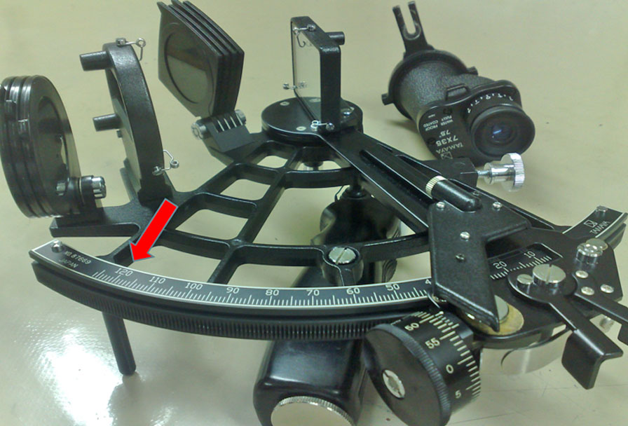
If the arc of a marine sextant is up to 60 degrees, why is the graduation up to 125 degrees?
If the arc of a sextant measures 60 degrees, it means that the total angular range covered by the arc is 60 degrees. However, the graduations on the arc are typically marked from 0 to 125 degrees.
The reason for this is the principle of double reflection. Marine sextant uses two mirrors to reflect the image of the horizon and the celestial object into the telescope.
When a ray of light is reflected twice by two mirrors in the same plane, the angle between the first and the last rays is twice the angle between the two mirrors.
Brief history
Early traders, navigators, and sea explorers tried to find their way across the vast seas using different instruments. From astrolabe to cross-staff and octant, each tool represented a step towards the development of the marine sextant.
The British instrument maker John Bird built the first navigational sextant in the year 1757. It consists of a mahogany frame and ivory used as a scale. Like many early inventions, this design was crude and heavy. The user must have a socket fitted on his belt to act as a means of support.
The legendary Captain James Cook made use of John Bird’s sextant during his iconic voyages which made several major discoveries during the 18 century.
Today, the modern marine sextant is lighter and easier to use. It has become more accurate, reliable, and user-friendly. Some variations even have illuminated scales and digital readouts.
Parts of a Marine Sextant
A marine sextant has 14 basic parts. It’s important to familiarize yourself with them so you know what they do and how they work.
Here are the 14 basic parts of a marine sextant:
1. Frame – The main structure of the sextant, typically made of metal or plastic, which holds all the other components in place. It features three legs that serve as a base when the sextant is placed horizontally.
2. Limb – The lower part of the frame that carries the arc. It has a cut on its outer edge with teeth, each representing one degree of altitude.
3. Arc – It may be inscribed on the limb, or it may be inscribed on a separate plate permanently attached to the limb. It is graduated along the limb from 0 deg to 125 deg “on” the arc allowing for angular measurements.
4. Index Arm or Index Bar – A movable arm attached to the frame, used to measure the angle between celestial bodies and the horizon.
5) Tangent Screw – Mounted perpendicularly on the end of the index arm, where it engages the teeth of the limb.
6) Clamp – A spring-actuated clamp that keeps the tangent screw engaged with the teeth of the limb. By applying pressure on the legs of the release, one can disengage the tangent screw. You can then move the index arm along the limb.
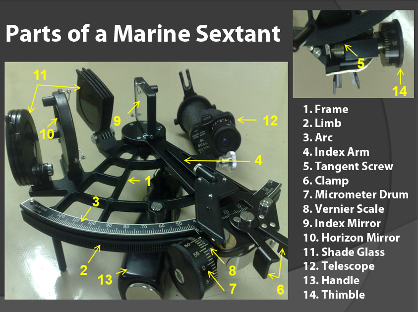
7) Micrometer Drum – Mounted on the end of the tangent screw which is graduated in minutes of altitude. One complete turn of the drum moves the index arm one degree of altitude along the arc. You can use the micrometer drum to make fine adjustments to the index arm.
8) Vernier Scale – A secondary scale that allows for more precise readings on the arc of up to fractions of a minute.
9) Index Mirror – A piece of silvered plate glass mounted at the upper end of the index arm, perpendicular to the plane of the instrument, with the center of the reflecting surface directly over the pivot of the index arm. It is used to reflect celestial bodies into the field of view.
10) Horizon Mirror – Another mirror positioned parallel to the index mirror, used to reflect the image of the horizon.
11) Shade Glasses – These are transparent filters or glasses that you can move into the line of sight at will, to reduce the intensity of light reaching the eye of the observer.
12) Telescope – An optical device attached to the frame, used to observe celestial bodies and align them with the horizon.
13) Handle – A grip or handle attached to the frame, providing stability and ease of handling during observations.
14. Thimble – The thimble’s function is to rotate the micrometer drum.
Sextant errors
There are two main errors of a sextant, adjustable errors, and non-adjustable errors.
Adjustable errors
Adjustable errors refer to the potential inaccuracies or deviations in the readings obtained from a sextant due to various factors that the user can correct or adjust. It accounts for any errors introduced by the instrument itself or the observer during the measurement process.
Here are four of its adjustable errors:
1. Index Error – This occurs when the index mirror or index arm is not perfectly aligned, resulting in a slight discrepancy between the observed angle and the actual angle. To correct this error, adjust the two screws at the back of the horizon glass.
2. Perpendicularity Error – This error occurs when the index mirror is not perpendicular to the plane of the instrument. To correct this error, adjust the first adjustment screw on the back of the index glass.
3. Side error – This error occurs when the horizon mirror is not perpendicular to the plane of the instrument. To correct this error, turn the second adjustment screw on the back of the horizon glass.
4. Error of Collimation – This error occurs less frequently than the three. It occurs when the telescope is not parallel to the frame of the sextant. Adjustment for non-parallelism is made to the collar, using two screws provided for this purpose.

Non-Adjustable Errors
The non-adjustable error of a sextant refers to the systematic error or deviation in its readings that the user cannot adjust or correct. It is a constant error that remains consistent regardless of any adjustments made to the instrument.
Non-adjustable errors can be caused by various factors, including inherent design flaws, manufacturing tolerances, or wear and tear over time.
1. Shade error – This is due to a lack of parallelism in the shade glasses near the index mirror.
2. Centring error – This occurs if the index arm does not pivot at the exact center of curvature of the arc. This can cause the index mark to be off-center when sighting the sextant on a distant object.
3. Graduation error – Occurs in the arc, micrometer drum, and vernier of a sextant that results from improper design or incorrect calibration. This can cause the sextant to read an incorrect angle.
4. Optical errors – May be caused by prismatic errors of the mirrors or aberrations in the telescope lenses. These errors distort the image of the object sighted, leading to an incorrect reading.
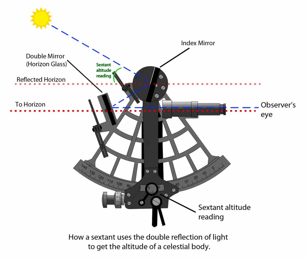
How a Marine Sextant Works
The optical principle of a sextant is based on the double reflection of light. When a plane surface reflects a light ray, the angle of reflection is equal to the angle of incidence.
When a ray of light hits two mirrors that are angled toward each other, it reflects off of both mirrors and then continues on its way.
The angle between the direction of the ray of light, before it hits the mirrors (angle of incidence) and the direction of the ray of light after it has reflected off of both mirrors (angle of reflection), is twice the angle between the two mirrors.
For example, if the two mirrors have an angle of 20 degrees to each other, then the angle between the first and final directions of the ray of light is 40 degrees.
As we mentioned above, this is why the sextant has calibrations of up to 125 degrees even though its arc is only up to 60 degrees.
How to use a marine sextant for taking sights
Using a sextant can be intimidating at first especially if everything you studied in school is all about its theory. Understandable since on land, many deck cadets can’t get a view of a nice straight horizon.
But at sea, we have everything we need for taking a sight. What’s more, all types of merchant ships have this tool, so you can practice them anytime.
Here are simple steps in using a marine sextant to obtain the altitude of a celestial body.
1. Prepare the sextant. Make sure that the sextant is clean, has no damage, and is free of dust, especially the mirrors.
2. Check the horizon. Observe the sky if the sun is not behind the clouds and if the horizon is clear.
3. Hold the sextant correctly. Hold the sextant vertically and look through the eyepiece. Adjust your grip if necessary so you can move the limb later without having difficulty.
4. Find the celestial body. Assuming it’s daytime, the best object for taking sight is the sun. At nighttime, identify the celestial body that you want to measure the altitude of.
5. Point the sextant at the celestial body. You may have to use the shades to protect your eyes from excessive sunlight.
6. Bring the celestial body into the horizon. Adjust the index mirror until the image of the celestial body aligns with the image of the horizon.
7. Swing the marine sextant left and right. This is to verify that the object is at the horizon. While swinging, the sun’s lower limb should slide tangent to the horizon.
8. Read the angle. The angle between the two images- the horizon and the celestial object, is the altitude of the celestial body. Read the angle from the scale on the sextant.

How to read the sextant
Reading the sextant is very simple. Once you have the observation of the celestial body, here’s how to take the reading of it for your position-fixing calculations.
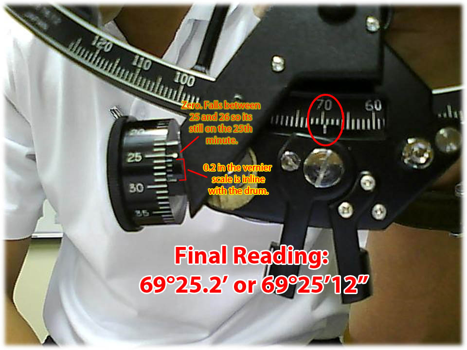
1. Degrees – Read it directly from the arc of the sextant. Check the marker and note which number it falls into. This one is the easiest to read.
2. Minutes – Read it directly from the Micrometer drum. Check the zero scale (one with a big white dot) in the Vernier reading and note where it falls to.
In the example below, it falls between 25 and 26. This means it’s still in the 25th minute.
3. Seconds – This can be a bit tricky. Read the seconds directly from the Vernier. Every line here is equivalent to 0.2 seconds.
Check the scale in the Vernier and observe which of the lines coincide 👉👈 with the graduated scale on the micrometer drum.
In the example below, the 0.2 scale is in line with one of the scales in the drum. Now, we have a reading of 0.2”.
Now we have a sextant reading of 69°25.2’ or 69°25’12”.
Today, fixing your position is very easy with the help of electronic equipment. You can even track a ship over the internet and get a quick overview of where they currently are. However, I still believe that using the old techniques still has a place in the maritime world.
Have you tried using a marine sextant? How did it go? More importantly, did you plot the ship’s position after taking a sight?
May the winds be in your favor.
A family man, he loves writing, reading, investing, and watching the golden hours while sailing.
0 Comments